Information
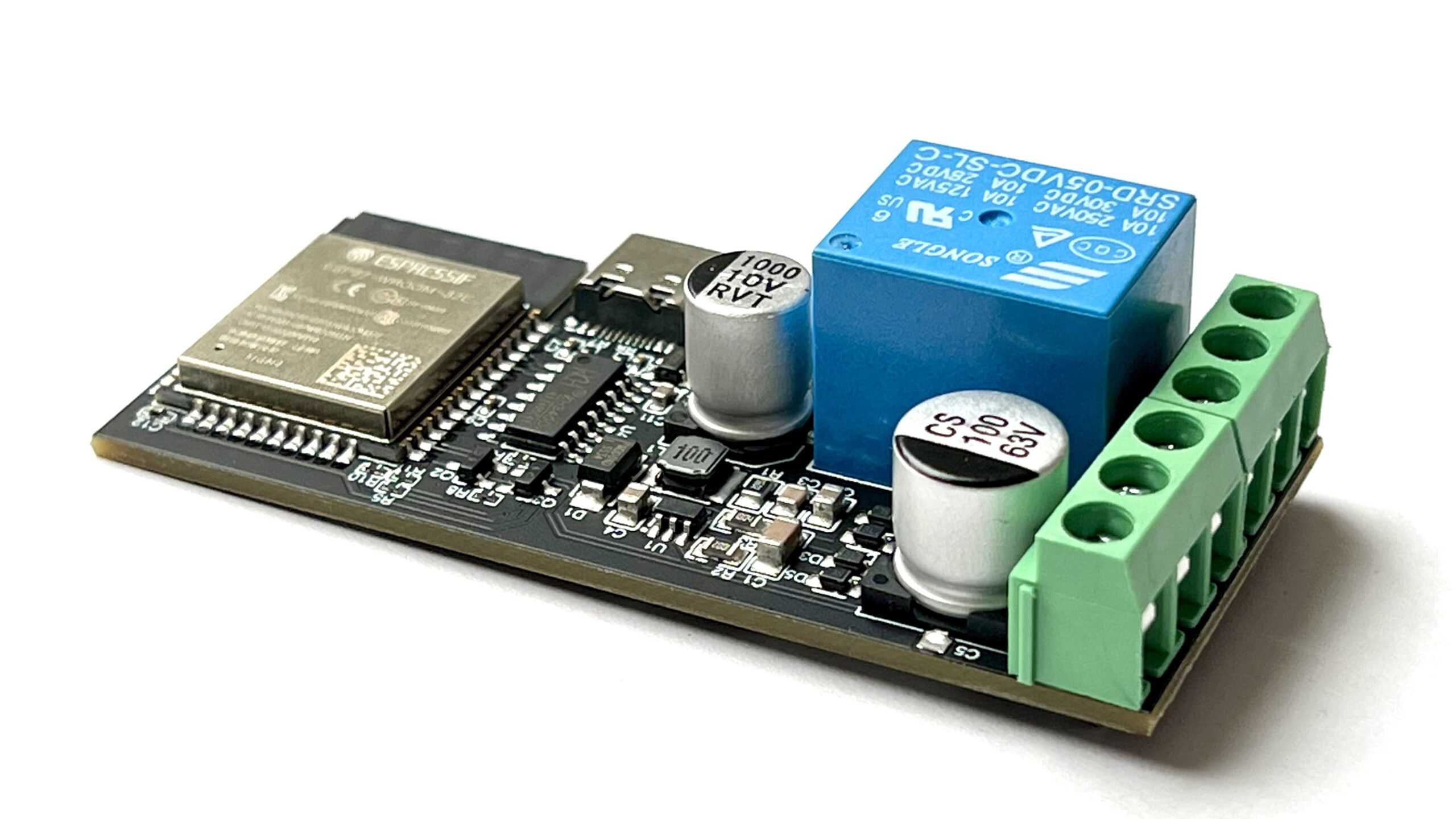
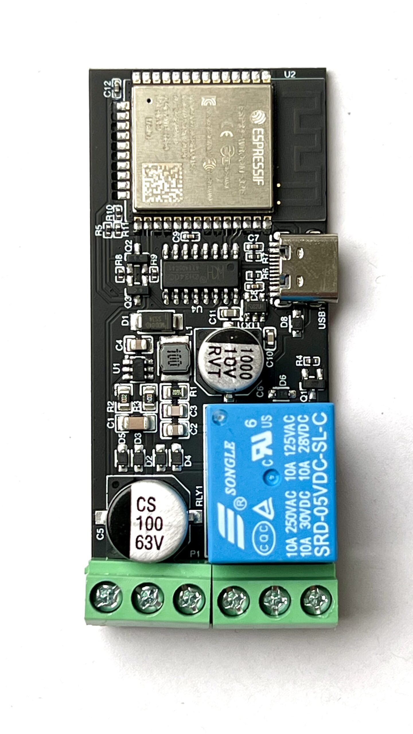
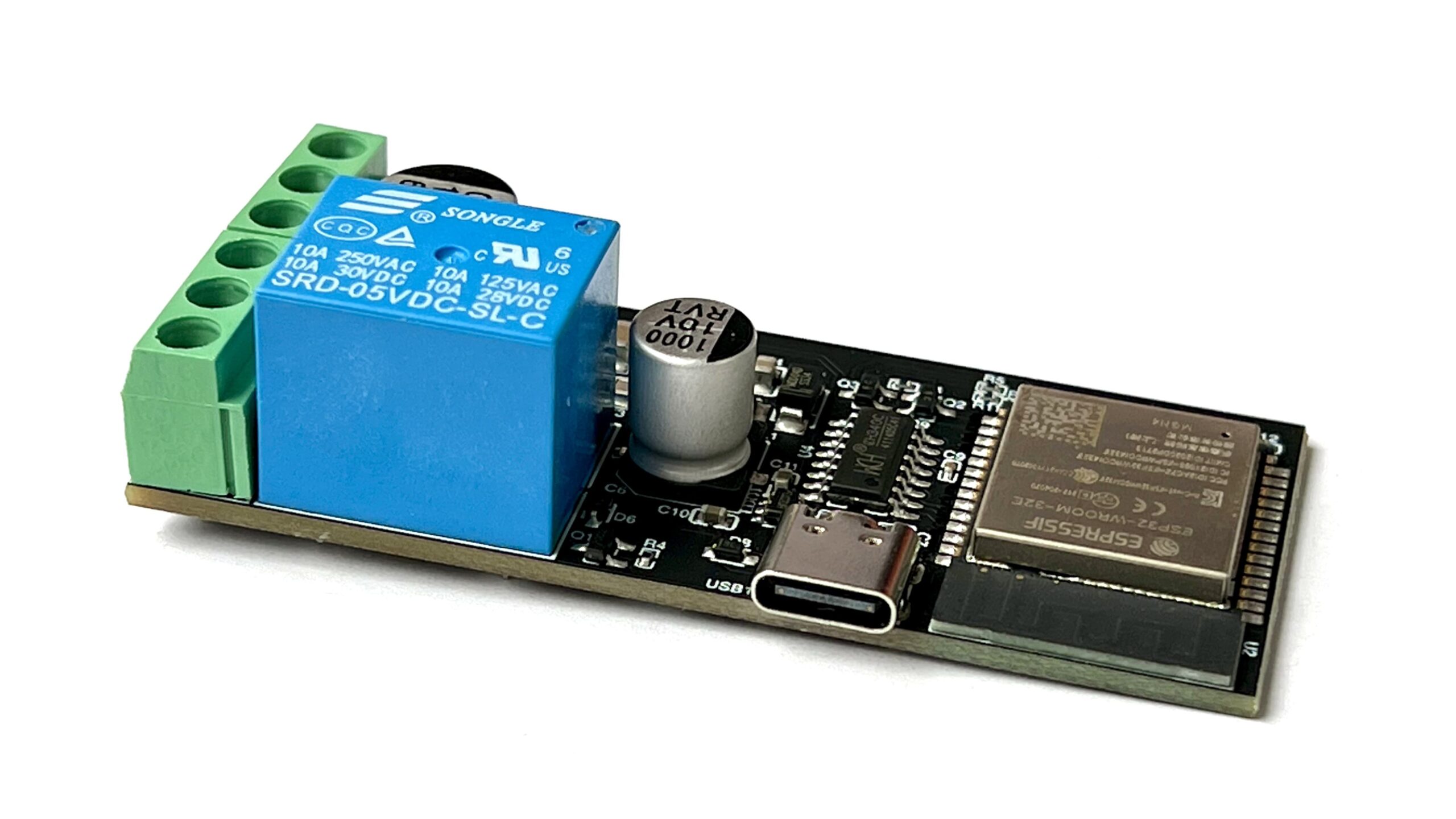
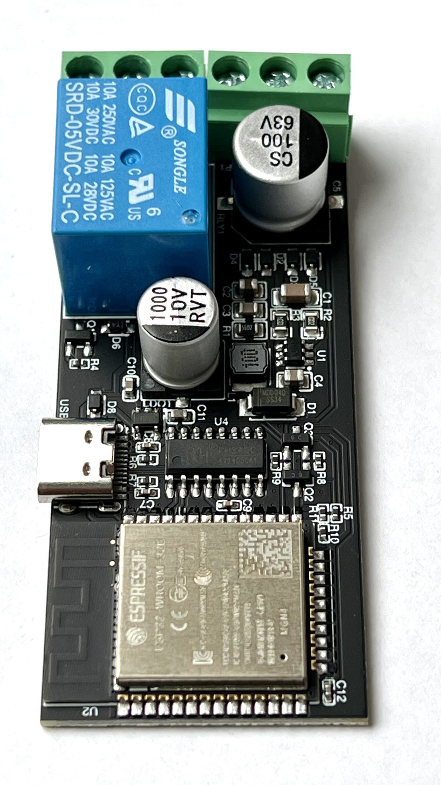
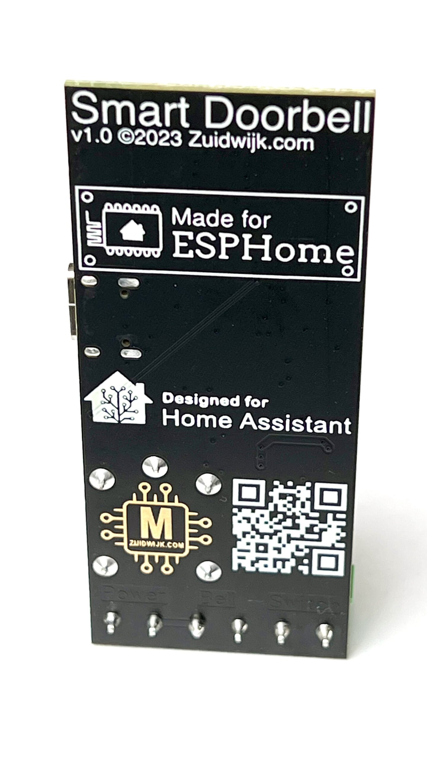
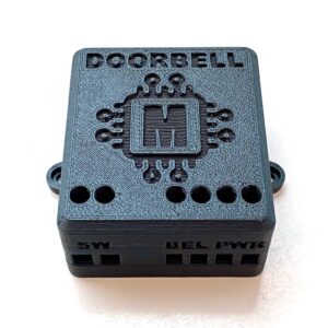
This doorbell is the successor of the previous version doorbell v2.0. It is 100% assembled and has now an ESP32 (ESP32-WROOM-32E) onboard.
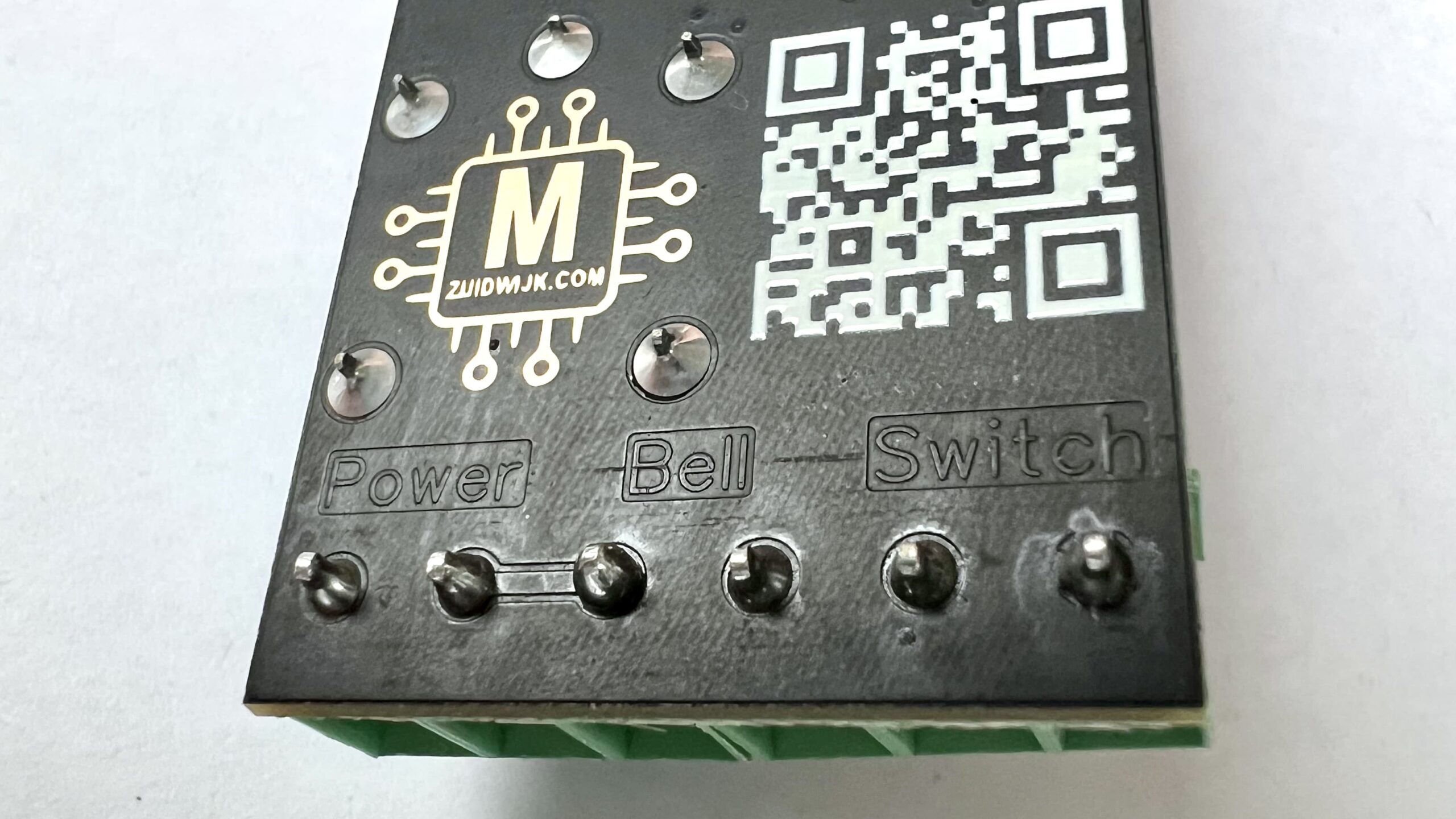
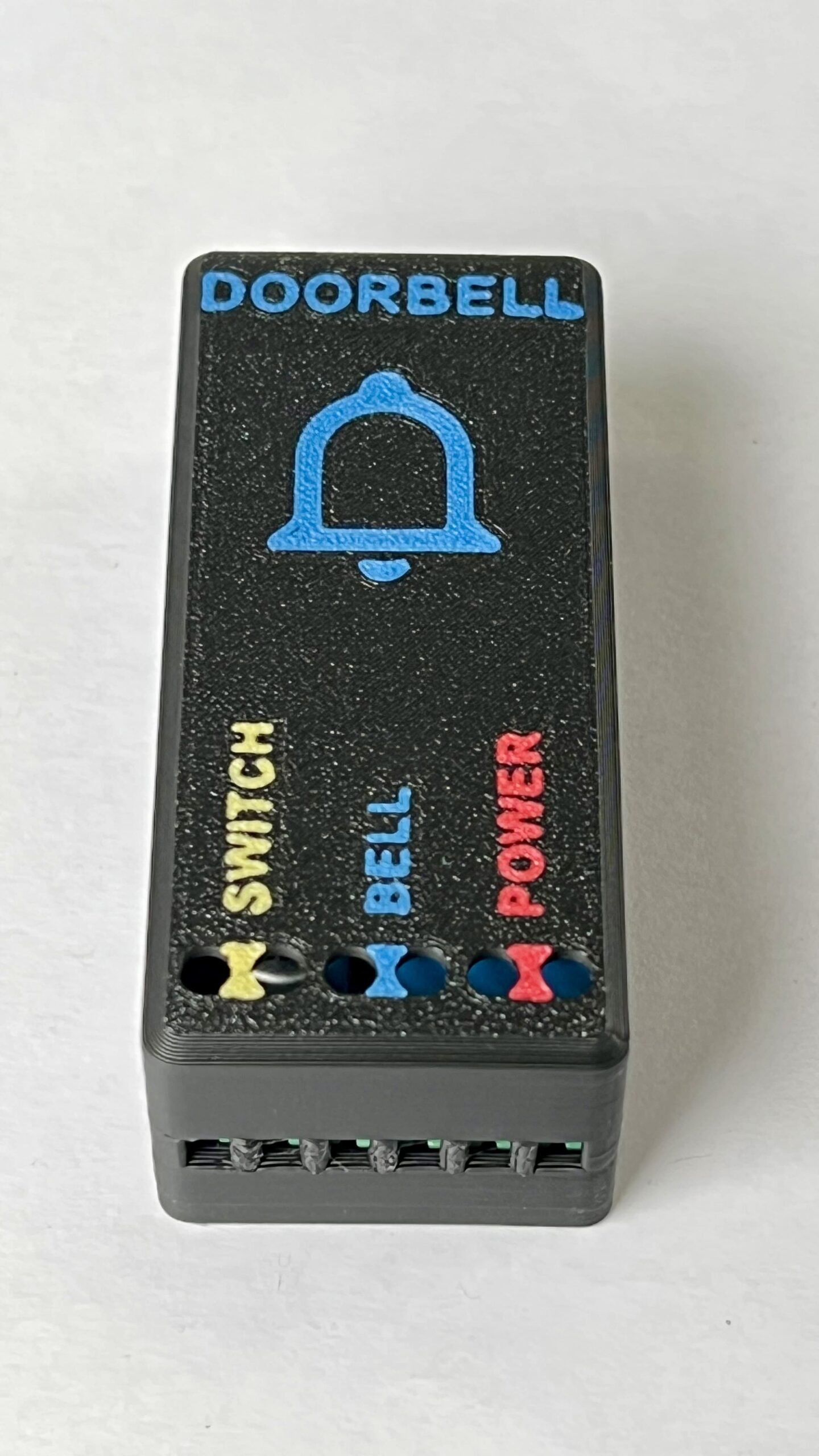
The doorbell has 3 connectors to make a “dumb” classic doorbell smart:
- Power: here goes the power from the doorbell transformator (AC/DC 40 volts max)
- Bell: here goes the doorbell (the input power goes via the relay to this connector)
- Switch: here goes the push button placed at the door (note: the push button cannot contain light)
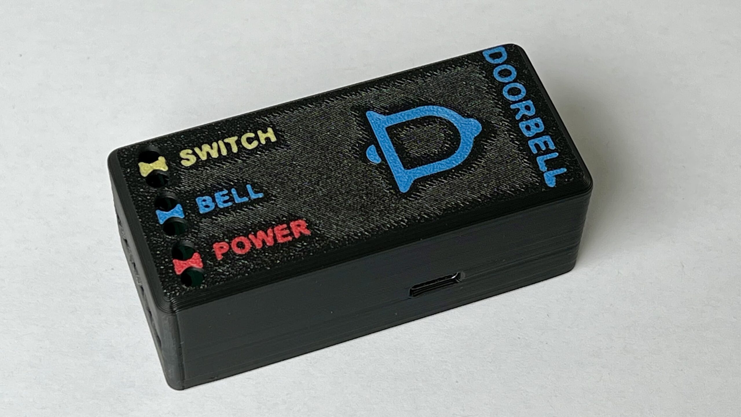
The Case
The case can be downloaded from Printables if you wish to print it yourself.
Technical information
There’s a new version of the doorbell, same form factor, but a small change in configuration.
1st edition
This is the version sold until around end 2023, begin 2024. This version has no led’s onboard
These are the used GPIO’s:
- GPIO4: switch input, active pulled up and not inverted. Directly connected to the switch connector and triggered via connection to ground.
- GPIO5: relay output
Full config is on GitHub
2nd edition
This is the current version, recognizable due of two led’s. One for power and one for the relay status.
These are the used GPIO’s:
- GPIO4: switch input, active pulled up. Controlled via a transistor, which is controlled through the switch connector (5v and ground).
- GPIO5: relay output
Full config is on GitHub
The config difference
The 1st version had an inverted trigger on GPIO4:
binary_sensor:
  - platform: gpio
    pin:
      number: GPIO4
      mode: INPUT_PULLUP
      inverted: true
The 2nd version has an non-inverted trigger on GPIO4:
binary_sensor:
  - platform: gpio
    pin:
      number: GPIO4
      mode: INPUT_PULLUP
      inverted: false
Support page
For flashing or more details, click here.

